


Motor Holding Brake Connection
A 24 V holding brake in the motor can be controlled directly by the drive. For proper function, check voltage drop, measure voltage at brake input and check brake function (on and off).
Brake voltage supply by using 24 V ±10% auxiliary voltage supply of the drive on X10. Minimum and maximum brake current see Electrical Data Brake output.
AKD2G offers motor brake outputs on connectors
|
Connector |
Usable for |
|---|---|
|
X1 |
Primary motor brake axis 1 or secondary brake for axis 2 |
|
X2 |
Primary motor brake axis 2 or secondary brake for axis 1 |
|
X4 |
Secondary motor brake axis 1, for single axis drives only Secondary Brake connector X4 |
|
|
Serious injury could result when the load is not properly blocked. The internal brake function does not ensure functional safety.
|


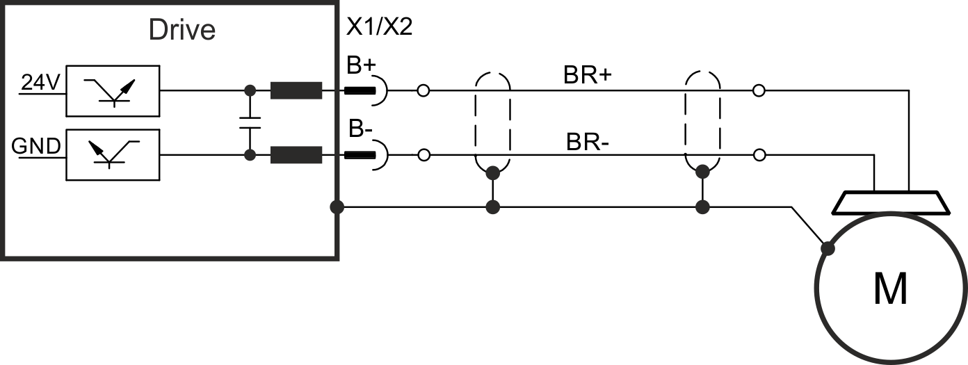
Pinout X1 / X2
|
Pin |
Signal | Description |
|---|---|---|
|
B+ |
BR+ |
Brake positive line |
|
B- |
BR- |
Brake negative line |
Wiring
Usually the brake lines are part of the Kollmorgen cable connections to X1 and X2 Single motor cable connection.
Functionality
The brake function must be enabled through a parameter. The diagram below shows the timing and functional relationships between the controlled stop signal, speed, and braking force. All values can be adjusted with parameters; values in the diagram are default values.
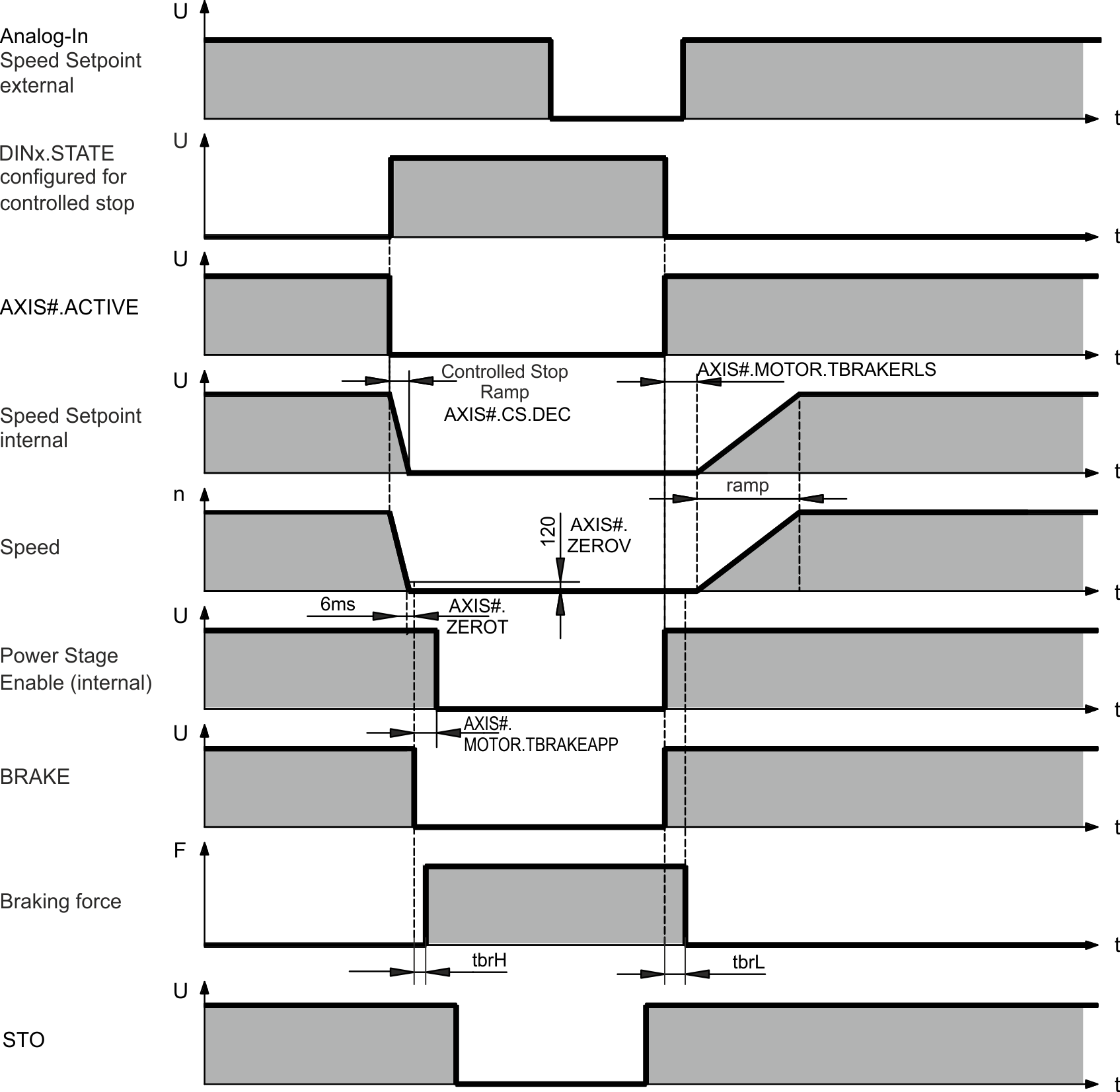
The drive speed setpoint is internally driven down an adjustable ramp (AXIS#.CS.DEC) to 0 V.
With default values the output for the brake is switched on when the speed has reached 5 rpm (AXIS#.ZEROV) for at least 6 ms (AXIS#.ZEROT). The rise (tbrH) and fall (tbrL) times of the holding brake that is built into the motor are different for the various types of motor.